Installing CanFly®
Congratulations on purchasing a CanFly® system. This tutorial will walk through all of the pieces you need to know to succeed in the installation.
Once completed please refer to the Tunning CanFly.
Using This Manual
The CanFly system is designed to upgrade a Lycoming 4 Cylinder engine with a modern, redundant electronic ignition and fuel injection system. The CanFly system comes complete with all components needed to upgrade an engine. However there are several components that will require the fabrication of electrical connections and fuel lines. Where you need to construct a part it is clearly shown in the instructions.
Experimental Aircraft Only
CanFly EFII systems are not certified and may only be installed into experimental aircraft.
Warranty
Your CanFly EFII electronic ignition is warranted for one (1) year from the date of purchase. Any unit returned must first receive a return authorization number prior to shipping. Kotuku Aerospace will repair or replace ignition modules within the warranty period that, in Kotuku Aerospace’s sole opinion, have not been subjected to abuse or any attempted field repairs. This warranty is limited to the purchase price of Kotuku Aerospace Limited hardware and does not cover the engine or other engine components that may be affected by defects or failure of the system.
Caution
The aircraft operator has the sole responsibility of determining how to appropriately and safely control engine operation. Nothing stated by Kotuku Aerospace Limits, its employees, owners, agents or affiliates should be construed as overriding or invalidating the engine manufacturer’s instructions.
Preparing your engine
If you have a new engine without any ignition of fuel components then skip to the section titled Parts to Prepare.
Otherwise read on.
Lycoming O-Series engines come with a large number of options, far too many to list.
However the engine should be prepared as a ‘core’ engine with the following is required:
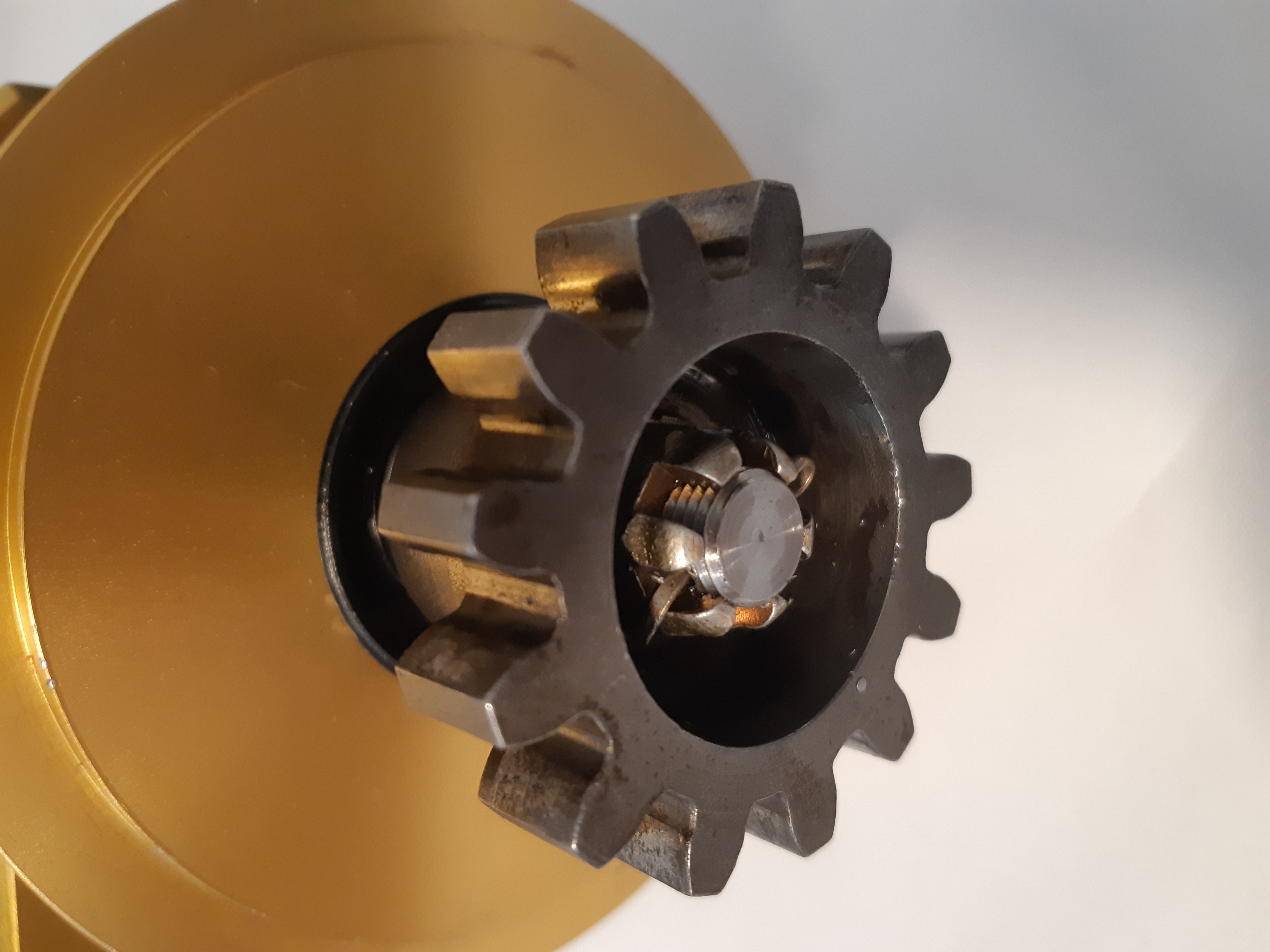
- Both magneto’s and associated impulse coupler must be removed from the accessory case. From the right magneto (if fitted) remove the drive gear. The impulse coupling drive gear is not used. A second drive gear must be purchased for the left mounted ECU.
- Remove all ignition wiring and spark plugs. The inhibit wiring may be used or removed back to the ignition switch.
- If the engine came with a mechanical fuel pump, ensure it is a fuel injection pump. Otherwise remove it as it must be replaced with a Lycoming fuel injection pump.
- Remove the carburettor or fuel injection controller.
- Remove the fuel divider if fitted, as well as all of the fuel injectors. If no fuel injection system is fitted remove the 1/8 NPT plugs for the fuel injector ports on the top of the engine.
Overview of the installation
Installing a CanFly system will take a reasonable amount of time. Particularly if the engine does not have any sensors installed already. The basic process is:
- Prepare the mounting for all components. This will be very installation dependent however the CanFly system is designed to be as close to an existing O-Series engine design as possible.
- Install the engine components. This is the fuel divider, fuel pump, EGT sensors, CHT sensors, Oil Pressure sensor, Oil Temperature Sensor, Spark plugs, ECU’s, Intake manifold and fuel injectors.
- Install the fuel lines and fuel injector lines.
- Install the CanFly wiring loom.
- Terminate the wiring for the mixture, ignition and inhibit wiring.
- Power on and set the ignition timing using the CanFly Commander application. Also set any custom programming needed.
- Test
The following sections deal with each of the steps in the above order. This assumes a new engine installation, or an upgrade with all of the old components removed.
Parts to Prepare
The CanFly kit comes with 2 ECU, and 2 Wiring looms. At the pre-shipment check one ECU will be marked as 'R' and should be installed in the right magneto mount. If the tag has been lost, don't worry you can configure the ECU to be either left or right with the CanFly Commander app.
Ensure you have the following:
- Inspect all of the CanFly kit and make sure none of the components are damaged. Check the delivery docket for all components and contact Kotuku if there is anything damaged or missing.
- If the engine does not have a LW15473 (or equivalent) mechanical fuel pump installed then make sure you have one available to fit.
- You will need 2 LW-15659 (or equivalent) drive gears. There will be one on the right magneto if the engine has them fitted.
- Your electric boost pump needs to be a 30psi pump. If you have one fitted and it is for a carburator, then change it.
- Access to the instrument panel and mag switches.
Installation
This step is best done after the engine has had all long-term storage and blanking plates removed. The installation is done using the following steps:
| Step | Action |
|---|---|
| 1 | Remove the fuel pump, or fuel pump blanking plate. |
| 2 | Ensure the fuel pump push rod, and associated eccentric cam are installed. If not remove the accessory case and install the components. |
| 3 | Install a Lycoming LW15473 fuel pump onto the rear of the engine. |
| 4 | Remove the magneto's or covers (if fitted). |
| 5 | Install the Left ECU. |
| 6 | Install the Right ECU. |
| 7 | Install the fuel distribution block on the top of the engine. |
| 8 | Install the injectors into the fuel injector ports. |
| 9 | Fit the intake throttle body, and connect the throttle cable. |
| 10 | Make the fuel lines from the mechanical pump to the fuel distribution block. |
| 11 | Make the fuel lines from the fuel distribution block to the injectors. |
| 12 | Make and install the spark plug leads. |
| 13 | Fit the CanFly wiring loom to each ECU. |
| 14 | Fit the panel mount USB adapter and mixture control. |
| 15 | Run the cables through the firewall and terminate. |
| 16 | Set the timing and load the default configuration. |
Installation step 1
Remove the fuel pump, or fuel pump blanking plate.
If you are installing the CanFly system on a new engine, then we recommend you request a LW15473 (or equivalent) fuel pump to be installed on the engine. If your engine has a LW15473 fitted then skip to step 4.
If you are doing an upgrade from a carbureted engine then you need to replace the low pressure (5 psi) pump with the LW15473 which delivers fuel at around 30psi.
If your engine has never had a fuel pump installed then remove the blanking plate from the accessory cover. Proceed to step 2 and check that the push rod is installed. Otherwise skip to step 3.
Installation step 2
Ensure the fuel pump push rod, and associated eccentric cam are installed. If not remove the accessory case and install the components.
The LW15473 fuel pump requires a push rod to actuate it. Once the cover is removed from the rear of the engine, check that the push rod that actuates the pump is
Installation step 3
Install a Lycoming LW15473 fuel pump onto the rear of the engine.
The LW15473 is also sold by Tempest as the 40296 pump. This is installed onto the accessory case.
When installing the pump, make sure the lever is engaged with the push rod. Failure to do this will void the warranty on the pump, and will likely damage other components.
Here is a very good video explaining how to install the fuel pump. It is for a stock installation, just skip the fuel lines as these will be fabricated in step 10.
Installation step 4
Remove the magneto's or covers (if fitted).
If you are upgrading an engine from a magneto system then you will need to remove the existing magneto's. Recover the LW-15659 drive gear from the RIGHT magneto. You will need to source a second one for the second kMAG to be fitted.
If you have Bendix Magneto's then you will need to source some 66M21195 clamps. These are available from Aircraft Spruce.
If you have a new engine then just remove the plastic covers from the rear of the engine.
Installation step 5
Install the Left ECU.
This sequence assumes that you can get to the screws that hold the Kotuku supplied wiring loom easily. On some installations there may be an oil cooler mounted to the back of cylinder 4 which can make it quite difficult to install the screws that hold the cable in place. If this is the case then attach the wiring loom that is installed in Step 13 to the ECU now.
The left ECU is installed with the 26pin connector pointing to the left of the engine as viewed from the rear of the engine.
Attach the drive gear to the kMAG along with the supplied Woodruf key and torque to 120 in. Lbs. Install the lock pin as shown.
Just fit the sealing gasket as provided and hold the ECU in place with the clamps. Torque the ECU clap bolts to 360 in. Lbs.
The orientation of the kMAG, other than the cable being to the left is not important. In Step 16 you will set the actual timing for the kMAG.
Installation step 6
Install the Right ECU.
Generally speaking there should be nothing that obstructs fitting the CanFly wiring loom to the kMAG on the Right of the engine. Unlike Step 5 where there may be an oil cooler. If there is something obstructing access to the Right kMAG the fit the cable as described in Step 13 to the ECU now.
The installation is the same as the Left ECU described in Step 5 however the the ECU is installed with the 26pin connector pointing to the right of the engine as viewed from the rear of the engine.
Installation step 7
Install the fuel distribution block to the top of the engine.
The Kotuku fuel distribution block sits at the end of the engine and is fitted with 2 fuel pressure sensors. These feed-back to the ECU the current fuel pressure as close to the injectors as possible.
The block is designed to fit on the end of the engine as shown here:
The unit is supplied with 2 AN4 bolts, washers and locaknuts. Torque these to 96 in. Lbs.
Installation step 8
Install the injectors into the fuel injector ports.
Standard cylinders come with a fuel injector port on the top of the cylinder. Our injectors are designed to screw into these ports and hold a standard Bosch injector.
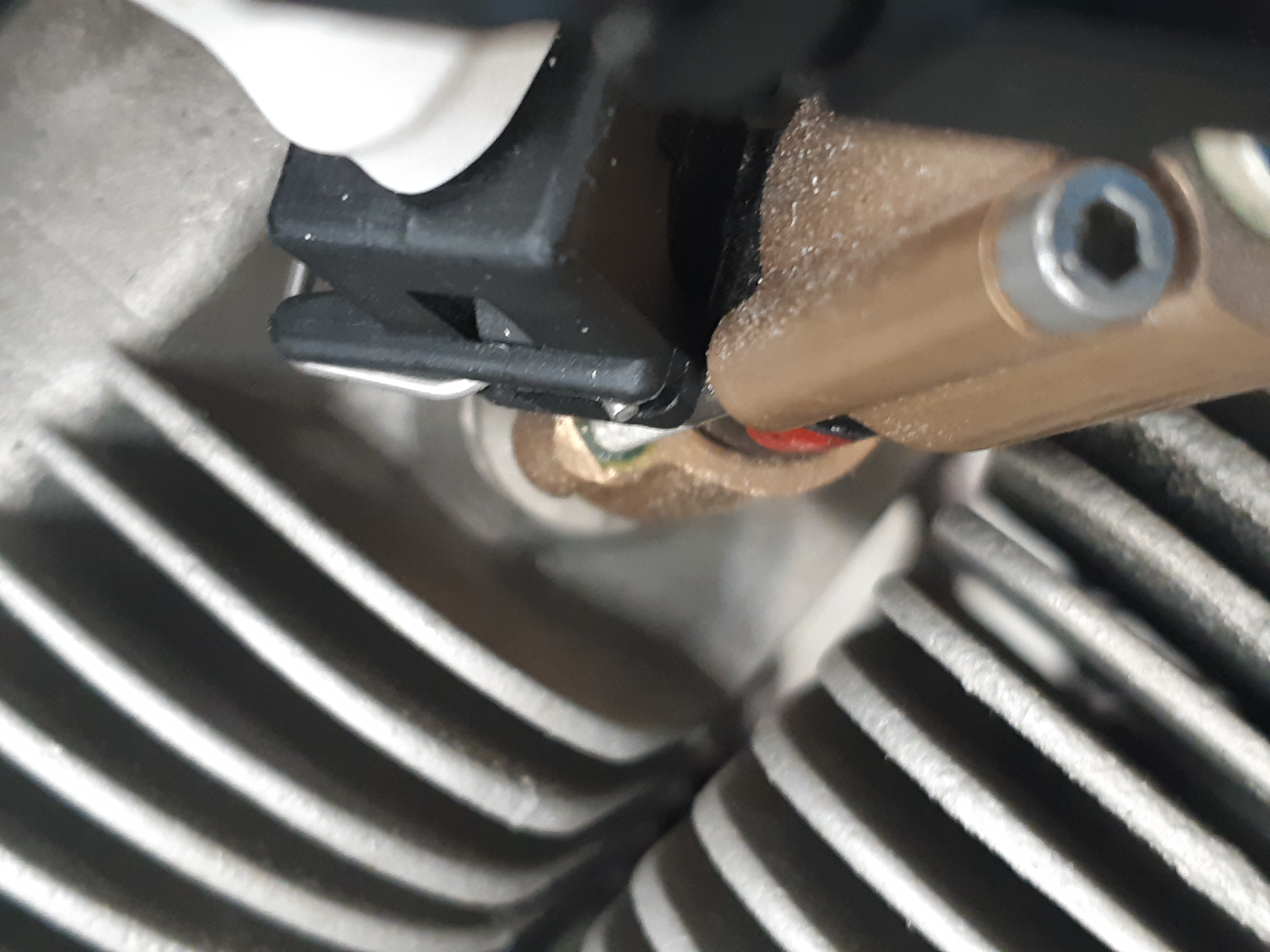
To install an injector the supplied injector must be dis-assembled so that it can fit as close to the port as possible. The electrical connector will not allow it to be turned and still clear the cooling fins.
To allow the injector base to be tightened in the port a torque plate is also supplied in the installation kit. There are 2 M3 x 8mm screws also in the kit along with a M1.5 allen key to tighten the screws.
This is how the injector will look once installed:
These are the things needed to be done.
- Unpack the injector and on the flow sheet provided, write the cylinder that the injector is to be installed in. These calibration values will be entered when the CanFly system is configured.
- Disasemble the injector. Use the M1.5 allen key to undo the 2 x 40mm screws that hold the injector together. Place the components separetely and make sure they are kept clean. The screws will have retaining compound added during final assembly.
- Fit the torque plate to the injector base using the 2 M3 x 8mm screws. The plate takes a 3/8" allen key and is used to install the base.
- Use Loctite 567 or similar thread sealant on the base threads. Do not use RTV or any other similar product on any of the fuel system components. Tighten the base to 40 in. Lbs. and ensure it is oriented as shown in the picture above.
- Remove the 2 screws and the torque plate. Insert the injector till it is homed, and install the injector retainer.
- Draw a line with a sharpie pen where the fuel line as shown in the photo above will run to the injector. Remove the cover and place Locktite 567 on the supplied AN833-3D fitting and screw tightly into the retainer aligning the flare with the line you drew with the sharpie. Note however it must be clear of the retainer screws!
- Place Locktite 243 super thread locker on the 40mm screws and insert them into the injector retainer and tighten into the injector base. Do not over tighten, they just need to retain the injector which will seat firmly into the base and retainer.
- This is an optional step. While the Loctite 243 is sufficient to hold the injector and retainer you may want to cut a small slot in the hex M3 screws suffient to pass a fine safety wire into. A Dremel 0.25mm cutoff wheel is good for this. You can then wrap a safety wire around the screws and between the injector and rest the wire into the slot in the screw. Safety wire as you would with any locked bolt.
- Repeat for all injectors on the engine. You may want to put caps on the AN822 fittings if there is a possibility of dust or debries getting into the fittings.
Installation step 9
Fit the intake throttle body, and connect the throttle cable.
Depending on the type of engine either a #4 flange (vertical induction) or a #5 flange (horizontal induction) will be provided with the installation kit.
This step will require the installer/builder to fabricate a suitable support bracket for the push-pull throttle cable. This is dependent on your engine installation. Below are some photographs of typical installations.
The #4 flange is designed to be the same size as a Marvel Schweber carburator and in Vans RV installations will bolt onto the FAB flange without any modifications.
The #5 flange is suitable for horizontal induction engines like the O-360, O-375 and O-390 engines. It has a scat tube connection that is sutable for fitting to an air filter box.
On the side of the throttle body there are 2 manifold pressure and temperature sensors. Each of these connects to a different ECU and provides full redundancy.
Installation step 10
Make the fuel lines from the mechanical pump to the fuel distribution block.
The mechanical full pump has an AN6 outlet on the left side of the engine. A suitable fuel line needs to be made to take the fuel from this point to the fuel distribution block which has a matching AN6 fitting.
Kotuku does not supply this fuel line. We recommend making it from 3/8" 3030 aluminium tube with a bulkhead fitting passing through the rear cooling baffle.
We do not recommend moving the position of the fuel distribution block as the length of the hoses from the block to the injectors need to be as short as possible so the fuel pressure sensors are as close to the injectors as possible.
Installation step 11
Make the fuel lines from the fuel distribution block to the injectors.
The kit will come with some Stainless Steel braided PTFE hoses and AN3 fittings. Each injector needs to have a hose fabricated to connect the AN822 fitting to the ports on the fuel block.
In addition we recommend using adel clamps to secure the middle of the lines to the push rod covers on the top of the engine.
The lines are flexible so that the vibration of the engine cylinders does not affect the life of the hoses.
Installation step 12
Make and install the spark plug leads.
Installation step 13
Fit the CanFly wiring loom to each ECU.
Depending on the tightness of the installation of the left ECU the cable may already be fitted to that ECU in step 5. Fit both ECU wiring looms to the Left and Right ECU's. Each loom has the following groups:
- Injector drive lines. There are 4 marked sets, one for each cylinder. They are terminated with a 2 pin connector.
- Fuel pressure sensor. These are located on the fuel distribution block. It is not important which one is used however it is probably best to connect the left sensor (looking from the rear of the engine) to the left ECU and vica-versa for the right ECU. If a fault should develop, it will make identifying the sensor easier.
- Intake sensors. This is a 4 pin bundle that terminates at the intake throttle body manifold pressure and temperature sensor.
- Power, mixture, tach and inhibit. These are 5 long wires. They are color coded to make connecting to the aircraft wiring as simple as possible. They are terminated in Step 14
- A CanFly bus connector. This is used for programming and data.
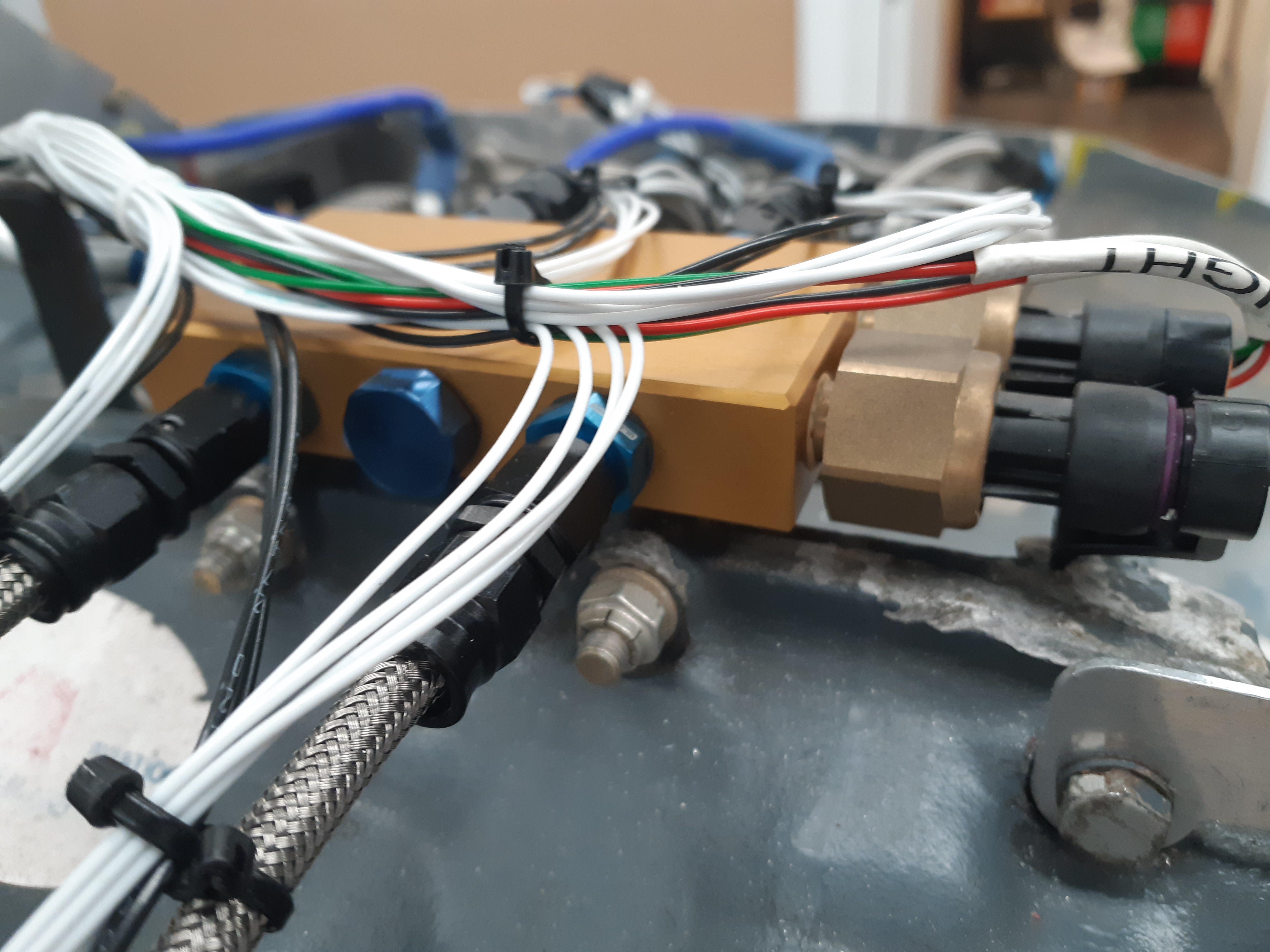
Each wiring loom is identical and should be routed close to the center of the engine so the injector lines are relatively even. Attaching the cables to the fuel line installed previously is a good idea. Use 2 cable ties, one of which is a spacer to stop the cables chafing.
We recommend running all wires through a grommet and then making an inverted U-Shapped notch in the cooling baffle to hold the grommet in place. This will allow the baffles to be removed without disturbing the wiring. The grommet also acts as a spacer to stop the cables chafing.
Run the 2 sensor cables to the throttle body and clip securely to the engine components.
Installation step 14
Fit the panel mount USB adapter and mixture control.
A standard kit includes a 2.25" panel mount control that has a CanFly to USB converter that will be used to configure and monitor the system. This includes a mixture control that allows for manual control of the mixture of the engine.
If it is desired to fabricate a quadrant style mixture control Kotuku can supply a kit with a dual gang 10k linear potentiometer that has an arm that can attach to a push-pull cable. As well a stand-alone (not panel mount) CanFly USB adapter will be provided.
These instructions are assuming the 2.25" control will be fitted.
The CanFly bus is a 'daisy chain' bus where each device is attached to a single 9 pin connector that has Can bus in and Can bus out. The last device has a 120 ohm termination resistor installed on the Can bus out pins. In addition the CanFly connector has Can power and ground.
In a CanFly system without any other devices such as the Engine Data Display or Engine Data Unit the power and ground is not used. However the units will pass the power through.
A kit includes a 5ft CanFly cable that has 3 connectors. There are 2 that are 6" appart that must be connected to the CanFly ECU's. It is not important which one connects to each connector. The end connector already has a 120ohm termination resistor.
The CanFly bus cable should be bundled with the 8 other flying wires that are to go through the firewall.
Installation step 15
Run the cables through the firewall and terminate.
A hole must be made in the firewall to carry the flying leads from the ECU to the instrument panel. Depending on the installation, if a Engine Data Unit is being installed as well the size of the hole may be different. We however recommend that a 1" hole so that if required at a later date there will be a hole large enough for engine sensors.
The 1" hole is also large enough to fit the CanFly bus connector through without the cover installed. The cover must be removed in any case as depending on the install, another daisy chain segment may be installed or a termination resistor will be installed.
These instructions assume a basic install. If you are installing an Engine Data Display and Engine Data Unit then please go to Installing an kEDU and kEDD and then return here.
We recommend using a firewall pass through for all cables. We use a stainless steel passthrough, available from Aircraft Spruce which provides good results. There are however many other types available.
Prior to routine the cables we recommend identifying the 4 wires to the ECU. A simple cable tie over the right ECU wire bundle is sufficient.
There are 5 wires from an ECU:
| Color | Usage |
|---|---|
| Red | ECU power. +12v Connect to a 2A circuit breaker |
| Black | Common. Connect to the aircraft common (ground) |
| White-Green | Mixture. Goes to the mixture control (see below) |
| White-Black | Inhibit. Connect to the inhibit switch or ACS keyswitch. Ground is inhibit |
| White-Yellow | Tach. If a kEDU is installed then connect to the tach input (left/right) or to your EIS |
Mixture control
The mixture control has a 4 pin connector. The pins are:
- +12V to CanFly bus. If a kEDU and kEDD are used then this should connect to the avionics bus. We recommend using a TCW IBBS or similar product to provide instrument backup power.
- Left Mixture. Connect this to the White-Green wire from the left ECU.
- Ground. Connect this to the aircraft ground bus. Must be connected in even if the +12V is not connected.
- Right Mixture. Connect this to the White-Green wire from the right ECU.
This photo shows how the mixture connector is wired:
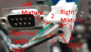
The connector is a TE Connectivity 1-770968-1 connector and detailed instructions on how to assemble and crimp the connectors can be found here.
CanFly wiring diagram with a battery backup system.
This diagram shows the recommended wiring for a CanFly system with a TCW IBBS-12V-6AH that will power the Engine Data Unit, Engine Data Display and the CanFly ECU's independently of the main bus power.
We expect this design to give at least 1 hour of operational time of the system. The ECU generators will provide all of the power above around 1500 rpm so the time of the battery will only be limited by the EDU and EDD power. This is only 750ma so should last at least 3 hours.
There is a cut-off point for the ECU generators at around 1200 rpm where reliable operation will not be guaranteed. This system will allow the aircraft to operate below the RPM limit so long as there is enough charge in the IBBS battery.
Please refer to the TCW industries documentation for complete details of the IBBS.
Installation step 16
Set the timing and load the default configuration.
Firstly download the CanFly® Commander installation package from the Kotuku Aerospace website. This tool contains two applications that are needed to configure, tune and maintain the CanFly® system.
- The Commander application which is used to configure the devices connected to a CanFly® bus.
- The Update application which is used to update the firmware on a CanFly® connected device.
The CanFly Commander allows you to perform 3 critial tasks:
- Change the type of kMag® that is installed. A CanFly® kit comes with a left and a right device. These are configured during testing. However if a replacement kMag® is to be installed, it can be changed using the CanFly® Commander application. The tool used to make the change can also be used to check the inhibit lines work post installation. Please refer to the section in the Commander usage guide that deals with this applet.
- Load a kMag® configuration file and upload it to the devices. It is critically important that both devices are configured using the same parameters. The Commander usage guide deals with loading the XML formatted configuration file, and sending it to the kMag® devices.
- Display the operational details of all devices on the CanFly® bus. Before the engine is started the CanFly® Commander status page should be checked to ensure all parameters are within expected limits.
Once it is checked that the installation is completed, the engine can be started. On the first start it may take a while for the fuel to be delivered to the engine and a start accomplished. Subsequent starts will be much quicker however.
Be cautious of the cranking performance and don't overheat your starter motor during this period.
Once started, allow the engine to idle at around 1200rpm anc check that all temperature and pressures stabilize. After around 5 minutes, shut it down and check for any oil leaks. During the fast idle of the engine, if there are any signs of fuel leaks, shut the engine down immediately and correct the issue before a restart is attempted.