This document deals with installing a Engine Data Display and Engine Data Unit into a CanFly system. It assumes that the CanFly installation step 14 is being done and the user wants to install the engine monitoring system.
Using this document
This document assumes you are installing a Kotuku Engine Data Unit and Engine data display into an existing aircraft. If you are removing any old instruments then we recommend that that is completed and the airfrane/engine be returned as close to stock as possible.
This document runs through the individual steps that are needed to be done. Installing commisioning of the system takes quite a while. We recommend allowing suficient time to do the work in a professional manner, and not rushing any step.
Recommended practices
Location of the EDU
The EDU should be located on the cockpit side of the firewall. The unit is not sealed and is not designed for high temperature operation. If it is necessary to locate the unit on the engine side of the firewall then it must be placed as far away from the exhaust system as possible. It also cannot be located where any water or oil can reach the EDU covers.
If the EDU is placed onto the firewall and it is made from thin gauge stainless steel there is a chance the stainless steel will crack over time. Please ensure a doubler plate or other means of rigidly affixing the EDU is provided.
Firewall penetrations
We recommend that a 1" diameter hole with a suitable firewall penetration be fitted. There are a lot of sensor cables that must be connected to the EDU and a 1" hole size is the best solution. Once the EDU is commissioned, the remaining hole should be filled with a high temperature hole sealant.
CAN bus wiring
The CAN bus is a daisy-chain system and we assume the end of the daisy chain will be either the EDU or kMAG's. In either case the bus must be terminated with a 120 ohm termination resistor. A pair of resistors is available for part number 16-20002, these are pre-crimped.
Tefzel wire to be used
We recommend the us of aviation grade 22ga Tefzel wire for all connections to the EDU. The electrical wiring of the EDU is quite specific, and requires the EDU to be 'earthed' to the engine to help reduce noise. Since this connection must go through the firewall, Tefzel wide should be used.
Crimped connections
Where possible the connections to the EDU should always be made using crimped connections. This can be difficult with the use of small 22ga pins on the large 60 pin connector. Kotuku provides wires that are to be trimmed to length and terminated with small 1/8" ring eyelets for the thermocouple probes. These can be crimped with good quality crimping tools.
If you need to solder connections please read the recommended practices for aviation wiring to determine how to make robust electrical connections.
Overview of the installation
- Mount the EDD onto a 3.5" panel opening.
- If you are using a CanFly EFII system then the CanFly system will cover installing the USB port that is also used to configure the EDU. Otherwise install the USB port.
- Mount the EDU in a suitable location.
- Measure the cable-runs to determine if special cables are required. Depending on what you ordered a set of cables will be provided for you.
- Mount the sensors that are needed.
- Install the engine temperature probes, and optionally the OAT probe.
- Complete the wiring.
- Configure the EDU and test.
Installing the Sensors
Optional sensors
If you have a kMAG system then that system includes the Manifold Pressure sensor and Fuel Pressure sensors. Otherwise you will be provided with a 150psi sensor for Manifold Pressure and a 50psi sensor for Fuel Pressure.
Sensor list
- EGT sensors (4 or 6). These are K-Type sensors.
- CHT sensors (4 or 6). These are K-Type sensors.
- Oil Temperature sensor. This is a K-Type sensor.
- (Optional) OAT sensor.
- Current shunt for battery charge/discharge.
- Oil pressure sensor.
- (Optional) Fuel pressure sensor.
- (Optional) Manifold pressure sensor.
- Fuel flow sensor
Mounting the sensors
All sensors should be rigidly mounted. The Current shunt should be mounted to an metal backing plate with the provided thermal compound.
The pressure sensors should all be mounted to a 1/8 NPT bulkhead fitting attached to the firewall. A 1-1/2" x 1-1/2" x 1/8" angle bracket makes a very good rigid mount.
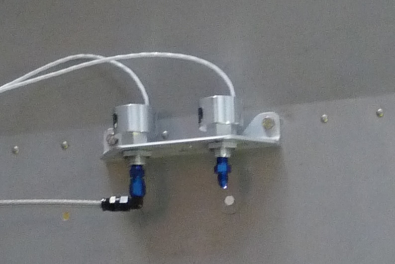
Where the sensor is mounted behind the firewall, use a 1/8 npt firewall penetration in the firewall material.
Never mount any pressure sensors directly to the engine
Always run an AN-4 line from the engine pressure port (Oil pressure) to the firewall mounted pressure sensor.
The torque value for the 1/8npt connector is 2 turns from finger tight. Please coat the threads with Locktite 567 thread sealant prior to installation.
It is recommended that a restrictor be fitted to the AN-4 Nipple on the engine so that in the event of a broken hose or fitting a catastrophic loss of oil occurs.